Guardium appliances are shipped with the software installed, and with an initial configuration as specified during the purchase process. This topic is organized as a series of installation steps that allow an administrator to completely configure the Guardium appliance. The initial configuration steps are performed using a local connection to the unit. The remaining configuration activities are performed over a network connection using a Web browser.
Before installing an appliance, read through this overview and then follow the complete set of steps:
Once you have read through this topic and gathered all necessary information, keep a copy of that information for easy reference in the event you need to reinstall the Guardium appliance later.
To initially configure the Guardium appliance:
Use the console to set the unit’s network configuration.
Place the appliance in its final network location and continue with the remaining configuration steps.
To set the initial network configuration for the unit, use the Guardium Command Line Interface (CLI), which is available from the serial port or on the system console.
To use a PC keyboard and monitor:
Attach a PC video monitor to one of the video connectors. There is one on the front of the unit and one on the back.
Attach a PC keyboard with a PS/2 style connector to the Keyboard connector on the back of the unit, or attach a USB keyboard to a USB connector on the front or back of the unit.
To use the serial port: Use a NULL modem cable to connect a terminal or another computer to the 9-pin serial port on the back of the unit. The terminal, or a terminal emulator on the attached computer, must be set to communicate as 9600-N-1 (9600 baud, no parity, 1 stop bit).
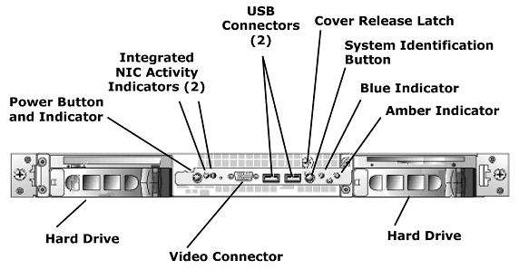
The appearance of the Guardium appliance varies slightly depending on the model number and the options purchased.
There are several important items to note on the Guardium system front, each of which is described in the table below.
|
Item |
Description |
|
USB Connectors (2) |
You can connect a USB keyboard to one of these for initial installation or when using the CLI. Also, a UPS can be connected to one of these. |
|
Cover Release Latch |
Use to remove the front cover. |
|
System Identification Button |
Use to locate a particular system in a rack. When pressed, the blue indicator lights on both the front and back of the unit blink. When pressed a second time, the indicators stop blinking. There is also a system identification button on the back of the unit. |
|
Blue Indicator |
Off -The system is off. Blue - The system is operating normally. Blinking - The system is identifying itself because the system identification button (see above) has been pressed. |
|
Amber Indicator |
Blinking - Indicates a fault with the system. |
|
Hard Drive |
Hard disk drives. There may be one on each side. See below for a description of the activity indicators. |
|
CD Drive |
CD drive for installing upgrades or patches. |
|
Power Button
|
Press to power the unit on or off. The indicator light may be: Off - The system is off and AC power is not connected. Blinking - A blinking green light indicates that the power is connected, but the system is not powered on. On - A solid green light indicates that the system is powered on. |
|
Integrated |
Activity indicators for the two integrated NICs, which may or may not be used, depending on your configuration. See Network Interfaces and Connectors below, for more information about the network connectors. |
|
Video Connector |
Connect a PC monitor here for initial installation or when using the CLI. You can also connect a PC monitor to the back of the unit or you can connect a terminal or a PC to the serial port on the back of the unit. |
The hard drives contain two indicator lights, on the lower right side:

The Activity Indicator blinks when the drive is being accessed.
For non-RAID applications, the Condition Indicator is solid green when the unit is powered on. For RAID applications, see below.
If RAID is activated, the two indicators on each of the hard-drive carriers provide information on the status of the SCSI hard drives. The following table lists the drive indicator patterns. Different patterns are displayed as events occur in the system. For example, if a drive fails, the drive failed pattern appears. After the drive is selected for removal, the drive being prepared for removal pattern appears, followed by the drive ready for insertion or removal pattern, and so forth.
|
Condition |
Indicator Pattern |
|
Identify drive |
The condition indicator blinks green four times per second. |
|
Drive being prepared for removal |
The condition indicator blinks green two times per second. |
|
Drive ready for insertion or removal |
Both indicators are off. |
|
Drive being prepared for operation |
The condition indicator is solid green. |
|
Drive predicted failure |
The condition indicator slowly blinks green, amber, and off. |
|
Drive failed |
The condition indicator blinks amber four times per second. |
|
Drive rebuilding |
The condition indicator blinks green slowly. |
|
Drive online |
The condition indicator is solid green. |
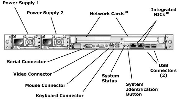
The appearance of the back of the Guardium system will vary slightly depending on the model and options purchased. The connectors described in the following table are present.
|
Item |
Desccription |
|
Power Supply 1 |
Attach the supplied power cord to the Power Supply 1 socket. If the back-up power supply is installed, attach the second supplied power cord to the Power Supply 2 socket. |
|
Network Cards* |
Two PCI slots on the back of the system may contain network cards, and one or two Integrated NICs may also be present. The use and location of all network cards is highly variable, depending on the options purchased. To connect network cables, refer to the network connection mapping document that shipped with the system. If you do not have this document, contact Guardium Support. |
|
USB Connectors (2) |
Connect a USB keyboard to either of the USB connectors for initial installation or when using the CLI. Typically, these are only used during the initial installation or for troubleshooting. A UPS can be connected to either of these USB ports. |
|
System |
Use this button to locate a particular system in a rack. When pressed, the system status indicator lights on both the front and the back of the unit blink blue. When pressed a second time, the status indicators stop blinking. There is also a system identification button on the front of the unit. |
|
System Status |
Blue - Blinking blue indicates that a system identification button (on the front or back of the unit) has been pressed. Amber - Blinking amber indicates the system needs attention due to a problem with power supplies, fans, system temperature, or hard drives. Off - The system identification button has been pressed a second time. |
|
Keyboard Connector |
Connect a PS2 keyboard here for initial installation or when using the CLI. You can also connect a USB keyboard to the back (see below), or to the front of the unit (see above). |
|
Mouse Connector |
Not used. |
|
Video Connector |
Connect a PC monitor here for initial installation or when using the CLI. You can also connect a PC monitor to the front of the unit or you can connect a terminal or a PC to the serial port (see below) on the back of the unit. |
|
Serial Connector |
For the initial configuration or when using the CLI, you can use a NULL modem cable to connect a terminal or another computer to this 9-pin serial port. The terminal, or a terminal emulator on the attached computer, must be set to communicate as 9600-N-1 (9600 baud, no parity, 1 stop bit). DO NOT connect a UPS via the Serial Connector. Only USB connections are supported for a UPS. |
Two PCI slots on the back of the system may contain network cards, and one or two Integrated NICs may also be present. The use and location of all network cards is highly variable, depending on the options purchased and the date the unit was built.
Guardium’s use of network interfaces is described below. To connect the network cables, refer to the network connection mapping document that shipped with the system or with any upgrade to the unit that involved changing one or more network cards. If you do not have this document, contact Guardium Support.
Always use ETH0 to connect to the LAN over which users will access the Guardium appliance. This is also the connection over which S-TAP and CAS agents will send data. A second network connection can be used to provide additional bandwitdth, or to provide for a fail-over capability (two separate options). The primary System IP Address is always assigned to ETH0, and the optional secondary System IP Address (set via the Administration Console) is always assigned to the highest numbered port. You can assign the primary IP address using the CLI, as described later in this chapter. To use a fail-over device, you must enable the high-availability option using the store network interface high-availability on command (see the CLI appendix).
Connect ETH1 to the first SPAN port. Optionally connect additional SPAN ports using the remaining connectors as necessary, in order.
Beginning with ETH1 & ETH2, Use each pair of connectors in sequence, one per TAP.
If installing Guardium inline to optionally provide database firewall functionality, use each pair of connectors beginning with ETH1 & ETH2 to insert the Guardium appliance between a group of one or more database servers and all of their clients.
Before beginning the installation and configuration of Guardium, there are a number of steps that must be taken. These steps include assuring that you have all of the parts of the Guardium system, gathering information about settings, and collecting necessary items such as hardware required to configure the Guardium system.
Prior to beginning Guardium configuration, select whether you will use a PC keyboard/monitor or configure through the serial port, as described above.
In addition to any hardware you may need that is specific for the selected configuration method, every installation and configuration requires the following:
Ethernet cable – To connect the unit to the network
Hardware shipped with the Guardium system, including:
Guardium system
Rack mount rails
Documentation for rack mounting the system
Metal front panel for the system
Power cord
Documentation for the Dell system
Dell Driver CD
The Guardium system behaves as a network protocol analyzer. It must be connected to a switch, hub, or other local area network (LAN) device through which the database traffic flows. This equipment should be the switch or hub nearest to the database client application system or the switch or hub nearest to the database server itself.
For the most comprehensive monitoring of database communications, it is recommended that the Guardium system be located as close as possible to the protected resource: the database. If placed near the database client system, the Guardium system will see all traffic to or from that client and any of the databases with which it communicates. If placed near the database server, the Guardium system will see all traffic to or from any client to the database server.
In order for the Guardium system to function properly, it must be able to collect the database communications that pass through the network segment on which it is connected. On a LAN that is implemented on a network hub, the Guardium system can view and collect network data packets. On a LAN that is implemented with network switches, viewing and collection of these data packets will not occur unless the switch is specifically configured to allow such actions.
If the Guardium system is placed on a switched network, that network switch must be configured to mirror all traffic to and from the databases to be monitored, to a port on which the Guardium unit will be connected. A network administrator will be able to perform this configuration. Consult your switch vendor’s documentation on the exact method to perform this configuration. Some vendors call this mirroring feature Port Mirroring or Switched Port Analyzer (SPAN).
If the Guardium database firewall will be enabled, the system must be installed inline, such that all client traffic to the protected servers passes through the Guardium unit.
The Guardium system provides administrative access from its first network interface card, whose connector is labeled ETH0, and optionally from its last network interface card. The number of the last interface card varies, depending on what types of cards are installed (one-, two-, or four-port cards are available).
Database traffic is monitored either:
Using SPAN ports connected in sequence to ETH1, 2, 3, etc. , OR
Using consecutive ETH connector pairs (1 2, 3 4, etc.), either to monitor traffic via network TAPs, or to install Guardium inline (in the latter case allowing it to be configured as a database firewall).
The network administrator:
Provides an IP address for the ETH0 connection to the desktop LAN, and optionally an IP address for a secondary management interface connection.
If Guardium will be configured to function as a database firewall, centralizes all traffic to and from the databases to be protected, such that the Guardium unit can be inserted between all incoming and outgoing traffic for the resources to be protected.
If Guardium will not be configured as a database firewall, configures one or more SPAN ports or network TAPs for use by Guardium.
Provides the default router IP address.
Provides DNS server IP addresses for from 1 to 3 DNS servers.
Adds the new Guardium system to the company DNS server.
If an NTP server will be used, provides its host name (you cannot specify an IP address for the NTP server).
Provides SMTP configuration information (for email alerts): IP address, port, and if authentication is used, an SMTP user name and password.
If SNMP will be used for alerts, provides SNMP configuration information: the IP address of the SNMP server and the trap community name to use.
The Guardium administrator:
Coordinates with the network administrator to connect the desktop LAN to ETH0, and to the optional secondary interface (if used).
With the network administrator, connects the SPAN port(s), or uses one or more ETH pairs (1 2, 3 4, etc.) to either monitor traffic from network TAPs, or to insert the Guardium unit between one or more database servers and their clients. (The last case is required to allow Guardium to function as a database firewall.)
Uses the Guardium administration console to ensure that the system and network settings are properly configured.
Different rails and rack mounting systems are available. See the separate document shipped with your unit for rack mounting instructions.
To configure the system initially, log into the unit and use the Guardium CLI. Later, you can use the Administration Console of the management interface to change most configuration settings.
The CLI language is not case-sensitive.
All CLI examples are written in courier text. For example: show system clock
Some command descriptions use delimiters to indicate which command arguments are mandatory and in which context. Each syntax description shows the dependencies between the command arguments by using special characters:
The < and > symbols denote a required argument.
The [ and ] symbols denote an optional argument.
The | (vertical bar) symbol separates alternative choices when only one can be selected. For example: store full-bypass <on | off>
Commands that handle a “state” setting accept and use the following state arguments:
on or off
up or down
enabled or disabled
active or inactive
1 or 0
You can abbreviate commands and keywords as long as you provide enough characters so the commands are not ambiguous.
For example: show can be shortened to: sho
Once interactive administrative access is physically connected (via console or serial port), turn on the Guardium system.
If a serial terminal is connected, no text will be displayed until the system has completely finished its boot process. At that point, a login prompt is displayed.
If a PC keyboard and monitor are connected, a splash screen is displayed. The Guardium system then loads the operating system and displays various text messages as it progresses (Setting clock, Loading default keymap, etc.)
Once the system has finished booting, press the Enter key to obtain the Guardium login prompt.
The only user account for the CLI is cli, with a password assigned as noted in your installation package.
Once you have logged in, you can start entering configuration settings.
To simplify the support process, we suggest that you keep the cli password assigned by Guardium. To change the cli password, use the store user password command. You will be prompted to enter the current password, and then the new password twice. None of the password values you enter on the keyboard will display on the screen. The cli user password must:
Be at least six characters in length.
Contain at least one digit character (0-9).
Contain at least one lowercase alphabetic character (a-z).
Contain at least one uppercase alphabetic character (A-Z).
Note that there is no way to retrieve the CLI user password once it is set. If you lose this password, contact Guardium Technical Support to have it reset.
For a complete list of commands and available through the CLI, see the CLI Appendix.
Users and remote components of Guardium access the system using one or two IP addresses. The primary IP address is for the ETH0 connection, and is defined using the following two commands:
store network interface ip <ip_address>
store network interface mask <subnet_mask>
Optionally, a secondary IP address can be assigned, but this can only be done from the GUI after the initial configuration has been performed.
The remaining network connectors are used to monitor traffic, and do not require the assignment of an IP address.
Configure the default network router by entering the following command, replacing default_router_ip with the IP address of the device that routes for the management interface.
store network routes def <default_router_ip>
Set the IP address of one or more DNS servers to be used by the Guardium system to resolve host names and IP addresses. The first resolver is required, the others are optional. Replace resolver_1_ip, resolver_2_ip, and resolver_3_ip with the IP address for each DNS server used:
store network resolver 1 <resolver_1_ip>
store network resolver 2 <resolver_2_ip>
store network resolver 3 <resolver_3_ip>
Configure the hostname and DNS domain name of the Guardium system. This name must match the hostname registered in the DNS system for the Guardium management interface’s IP address. If not, administrative access will only be possible via IP address.
Replace host_name with the DNS host name for the unit and domain_name with the DNS domain name:
store system hostname <host_name>
store system domain <domain_name>
There are two options for setting the date and time for the Guardium appliance. Do one of the following:
Date/Time Option 1: Specify an NTP server host name and enable its use (the NTP server specified must be accessible from the Guardium VA):
store system ntp server <ntpserver_name>
store system ntp state on
OR
Date/Time Option 2: Set the time zone, date and time. First, enter the following command to display a list of time_zone strings:
store system clock timezone list
Partial output follows:
Timezone: Description:
--------- -----------
Africa/Abidjan:
Africa/Accra:
Africa/Addis_Ababa:
Africa/Algiers:
etc...
The most common US time zone strings are:
America/New_York: Eastern Time
America/Chicago: Central Time
America/Denver: Mountain Time
America/Los_Angeles: Pacific Time
Locate and copy your Timezone string to the clipboard – do not include the colon character (:) – and repeat the previous command replacing the keyword list with your time_zone string. For example, for US Eastern time you would select America/New_York and enter the following command:
store system clock timezone America/New_York
Now use the following command to store the date and time, in the format: YYYY-mm-dd hh:mm:ss:
store system clock datetime <date_time>
For example:
store system clock datetime 2007-07-12 10:40:00
Note: This is not the preferred way to decode Kerberos-Encrypted Database User Names. See the Windows S-TAP help for more information. If you are unsure which approach will be used for Kerberos, skip this step for now (this can be configured later).
In an MS SQL environment, database user names may be encrypted by Kerberos. These names will appear as strings of hexadecimal characters in Guardium reports. The Guardium appliance can decode these names automatically if it has access to the Kerberos traffic and the feature is enabled, as described below.
To enable the automatic decoding of Kerberos-encrypted database user names, enter the following commands:
store local-stap on
store unit type stap
Ignore any messages about restarting the inspection core or inspection engines. The correct settings will take effect when you restart the server after all initial settings have been configured (as described below).
If the Guardium database firewall will be used, enable it using the following command:
store firewall on
Note: The Guardium database firewall is not available on all Guardium appliance models. The server must be equipped with bypass network cards, which can be configured to allow network traffic to pass if the server is unavailable. Also, A unit configured as an aggregator cannot provide firewall protection.
The store firewall on command (see above) automatically adds inline as a unit type attribute for the system. If you are not using the firewall but you are using one or more pairs of interface cards to read and forward traffic (as opposed to using a SPAN or mirror port), enter the following command to enable inline mode:
store unit type inline
This configuration is not recommended unless the server is equipped with bypass network cards, which allow traffic to pass if the unit is powered off or otherwise unavailable.
When inline access is enabled, you can control what happens to messages when the inspection engine (which tests policy rules against network traffic) is not running. By default, all messages will be forwarded. To block all messages when the inspection engine is down, use the following format of the store fail-policy command:
store fail-policy close
Before logging out of the CLI and progressing to the next configuration steps, it is important to validate the configured settings. Verify that each setting entered was entered and correctly, by entering the following sequence of show commands:
show network interface all
show network routes defaultroute
show network resolver all
show system hostname
show system domain
show system clock timezone
show system clock datetime
show system ntp all
show unit type
show firewall
Now that the basic system and network settings are configured, either stop the system and place it in its final network location, or simply reboot the system if it is already in its final network location.
To reboot the system, enter the following command:
restart system
The system will shutdown and reboot immediately after the command is entered.
If you will use a server certificate, continue with Step 4, below.
If you have purchased S-TAP for installation on database server systems, install those components now (see the S-TAP help book).
If you have not purchased S-TAP or after you have finished installing all S-TAP components, use the Guardium management console to begin setting up Inspection Engines and other Guardium components, as described in the remaining chapters of this document.
After you have configured the network settings and rebooted the system, you can obtain and store a server certificate following the process outlined below:
Use the CLI to create a Certificate Signing Request (CSR).
Submit the CSR to your Certificate Authority (CA) and obtain a server certificate in return.
If the server certificate returned by your CA includes the full trust path, skip ahead to step 4.4. Otherwise, store the CA certificate (and, if necessary, any intermediate certificates to the full trust path) on the Guardium unit. This must be done before storing the new server certificate.
Use the CLI to store the returned server certificate on the Guardium unit.
Each step is described in detail, below. Be aware that you perform the second step outside of the Guardium system, using whatever CA your company uses.
Use the Guardium CLI to create a CSR. Be sure to enter all information correctly and do not enter this command until after your network settings have been configured. The generated CSR will be a PKCS7 file encoded in PEM (base64 ASCII text) format, so you can copy and paste it easily.
To create the CSR:
Log in to the Guardium unit as the cli user, as described previously
Enter the csr command.
Reply to all prompts, which will be used in generating the request. Be aware that the common name (CN) is generated automatically from the host and domain name you assigned when configuring the unit:
What is the name of your organizational unit (OU=) ?
What is the name of your organization (O=) ?
What is the name of your city or locality (L=) ?
What is the name of your state or province (ST=) ?
What is the two-letter country code for this unit (C=) ?
What encryption algorithm should be used (1=DSA or 2=RSA)?
Regarding the last prompt, DSA was the only
algorithm that Guardium supported prior to version 7.0. You can find very
detailed information on the DSA and RSA algorithms by searching the web.
After you respond to the last prompt, the system displays a description
of the request, followed by the request itself, and followed finally by
additional instructions. For example:
This is the generated CSR:
Certificate Request:
Data:
Version: 0 (0x0)
Subject: C=US, ST=MA, L=Waltham, O=XYZCorp, OU=Accounting, CN=g2.xyz.com
-----BEGIN NEW CERTIFICATE REQUEST-----
MIICWjCCAhcCAQAwVDELMAkGA1UEBhMCVVMxEDAOBgNVBAgTB1dhbHRoYW0xETAPBgNVBAoTCEd1
YXJkaXVtMRUwEwYDVQQLEwxndWFyZGl1bS5jb20xCTAHBgNVBAMTADCCAbgwggEsBgcqhkjOOAQB
MIIBHwKBgQD9f1OBHXUSKVLfSpwu7OTn9hG3UjzvRADDHj+AtlEmaUVdQCJR+1k9jVj6v8X1ujD2
y5tVbNeBO4AdNG/yZmC3a5lQpaSfn+gEexAiwk+7qdf+t8Yb+DtX58aophUPBPuD9tPFHsMCNVQT
WhaRMvZ1864rYdcq7/IiAxmd0UgBxwIVAJdgUI8VIwvMspK5gqLrhAvwWBz1AoGBAPfhoIXWmz3e
y7yrXDa4V7l5lK+7+jrqgvlXTAs9B4JnUVlXjrrUWU/mcQcQgYC0SRZxI+hMKBYTt88JMozIpuE8
FnqLVHyNKOCjrh4rs6Z1kW6jfwv6ITVi8ftiegEkO8yk8b6oUZCJqIPf4VrlnwaSi2ZegHtVJWQB
TDv+z0kqA4GFAAKBgQCONsEB4g4/limbHkuZ5YnLn9CGM3a2evEnqjXZts4itxeTYwPQvdkjdSmQ
kaQlBxmNUsZOJZrq5nC5Cg3X9spa+BzFr+PgR/5zka17nHcxKXCjVjLk451L67KllXv61TUfv/bU
PKmiaGKDttsP2ktG4dBFXQdICJEGo0aNFCYn6qAAMAsGByqGSM44BAMFAAMwADAtAhUAhHTY5z9X
NiBAuyAC9PS4GzleYakCFF2kcfxfjX1BFy5I228XWMAU0N95
-----END NEW CERTIFICATE REQUEST-----
Please copy and paste this output to a file, starting at the BEGIN and END
lines, and use that file to work with your Certificate Authority in
obtaining a certificate. I will be expecting the incoming certificate to be in
PKCS#7 PEM format. Your CA will help you in receiving that format.
Once you have it, please use the "store certificate" command to
complete this operation.
Before continuing, check the Subject line to verify that you have entered your company information correctly. If you can submit a CSR online and obtain a server certificate quickly, remain logged in to Guardium. Otherwise, enter the quit command now to log out. Then log in again later after you have received the server certificate.
When copying the CSR, be sure to select the entire request (shown highlighted above), including the Begin and End request lines. Most CAs provide online signing services, so you will be able to simply paste the CSR to a text box. If not, paste the CSR to a text file or into an email in the appropriate location.
Be sure to have the server certificate generated as a PKS7 file in PEM (base64 ASCII text) format, since you will need to copy and paste it into the Guardium CLI.
Perform this step only if the server certificate returned from your CA does not include the full trust path.
Use the Guardium CLI to store the CA certificate and, if necessary, to store any intermediate certificates on the full trust path to the Guardium server. Certificates must be stored in hierarchical order, beginning with the CA certificate.
If you are not still logged in to the Guardium unit as the cli user, log in again as described previously.
Enter the store trusted certificate command.
The following prompt is displayed:
What is a one-word alias we can use to uniquely identify this certificate?
Enter a one-word name for the certificate and press Enter. The following instructions are displayed:
Please paste your CA certificate, in PEM format.
Include the BEGIN and END lines, then press CTRL-D.
Copy the certificate, paste it to the command line, and press CRTL-D. You are informed of the success or failure of the store operation.
If there are intermediate certificates on the full trust path to the Guardium unit, repeat steps 2 and 3 above for each of those, in hierarchical order.
Use the Guardium CLI to store the server certificate:
If you are not still logged in to the Guardium unit as the cli user, log in again as described previously.
Enter the store certificate console command.
The following information and prompt is displayed:
Please paste your new server certificate, in PEM format.
Include the BEGIN and END lines, then press CTRL-D.
Copy the server certificate, paste it to the command line, and press CRTL-D. You are informed of the success or failure of the store operation.
Enter the restart gui command to restart the GUI.